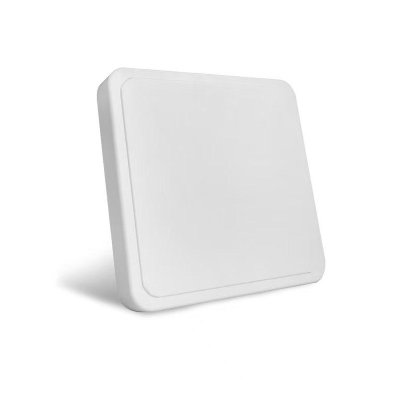
Consider this familiar on site headache for warehouse teams: forklifts travel through dock-door reader zones, yet few RFID tags trigger as expected. Readers and tags operate adequately, wiring passes most routine checks, but real-world performance still falls short. Quite often, the antenna is installed or positioned for a smaller coverage zone than the practical application demands.
The gap between basic antenna mounting and thoughtful fine-tuning frequently shapes what real world range long-range RFID systems can deliver. Drawing from RSTC’s hands-on deployments across warehousing, logistics and access-control use cases, this article explains how system integrators can optimize fixed UHF setups for more consistent reads past 15 meters, without overhauling existing hardware.
What Actually Limits Your RFID Antennas’ Read Range
Before adjusting anything, it helps to separate the variables that genuinely cap distance from the ones that are easy fixes. Four factors do most of the work: reader output power, antenna gain, cable and connector loss, and tag read sensitivity.
A 30 dBm reader paired with a low-gain antenna and twenty meters of thin coax will underperform a mid-power reader on a short, well-matched cable — the antenna and cable run are frequently the bottleneck, not the reader.
RFID Antennas built for long-range work are generally rated between 6dBi and 12dBi, and each step up in gain narrows the beamwidth while extending usable distance. A 12dBi linear antenna, for example, concentrates energy into roughly a 40-degree beam on both the H and E planes, which is what pushes read distance out — but it also means the antenna needs more careful aiming than a wide-coverage circular model.
Field Adjustments That Move the Needle on a Long Distance RFID Antenna
Getting a system to consistently clear 15 meters rarely comes down to one setting. These are the checks worth running in order, since each one affects the next.
- Match polarization to how tags actually pass through the zone. Linearly polarized antennas hold their gain advantage only when the tag orientation stays fairly constant, which fits vehicle lanes, conveyor lines, and dock doors. If pallets or cartons arrive at random angles, a circularly polarized antenna trades some peak distance for tolerance to that variation, and the trade is usually worth it in a busy warehouse.
- Push reader output power up in controlled steps. Most fixed UHF readers step output in 1dBm increments, often from around 5dBm up to 30–33dBm. Raising power gradually while watching the RSSI readout — rather than jumping straight to maximum — avoids over-illuminating nearby tags and generating false reads from adjacent lanes.
- Shorten and upgrade the RF cable run. Every meter of coax and every extra connector adds loss that eats directly into the antenna’s rated gain. On a 15-meter-plus target, a low-loss cable kept as short as the installation allows will often recover more distance than switching to a higher-gain antenna would.
- Recheck mounting height and tilt after the first test pass. A long distance RFID antenna aimed a few degrees off the tag path can lose several meters of usable range even with correct gain and power settings. Mounting brackets that allow fine tilt adjustment make this a five-minute fix instead of a re-installation.
- Account for the environment, not just the hardware. Metal racking, forklift bodies, and liquid-filled containers reflect or absorb UHF signal in ways a datasheet range figure doesn’t capture. Testing on site with the actual tagged goods, rather than generic test tags, confirms the distance a configuration will hold in production.
Matching Gain and Polarization to the Job
Distance and coverage width pull in opposite directions, so the “right” antenna depends on the layout more than a single spec number. A circularly polarized model in the 7–9dBi range suits warehouse entrances, retail floors, and library or archive checkpoints where tagged items move through at varying angles and a wider capture zone matters more than maximum throw.
A linearly polarized antenna in the 9–12dBi range fits vehicle lanes, parking barriers, and directional conveyor points, where tag orientation is predictable and the read zone needs to reach further down a corridor or lane.
RSTC currently supplies standalone options across this range, including the RS-B07CA01 (7dBi circular), RS-B09CA01 (9dBi circular), and RS-B12LA01 (12dBi linear) — the last of these operates at 902–928MHz, carries a VSWR of 1.5 or lower, and uses an N-Female connector with 50-ohm impedance, which keeps it compatible with most standard fixed UHF readers on the market.
Its IP64-rated ABS housing and a working temperature range of -40°C to +60°C are relevant details for anyone mounting it outdoors on a dock or gate rather than inside a climate-controlled facility.
For teams that would rather not manage reader and antenna as separate purchases, integrated units combine both into one enclosure, cutting down on cable runs and connector points — which, per the tuning steps above, is one of the more reliable ways to protect read range over a long lane or wide entrance.
Putting the Tuning Steps to Work
Reaching a stable 15-meter-plus read zone is less about buying the single highest-gain antenna on a spec sheet and more about working through power, polarization, cabling, mounting angle, and site conditions as a set.
Each adjustment on its own might only recover a meter or two, but stacked together they’re usually the difference between a reader that logs tags reliably and one that frequently requires manual rescanning as pallets move through the coverage area.
Teams sourcing antennas, readers, or complete tracking setups can review the current lineup of long distance RFID antenna models, or get in touch with RSTC for help matching gain, polarization, and mounting configuration to a specific site layout before committing to hardware.